i wouldn't say i'm as superstitious as most baseball players, but i was raised a bit on hellfire and brimstone and some things you can't shake... you don't need me to tell you these cert exams are difficult and require a great amount of effort, as well as a little prayer... i am not ashamed to say that before i begin an exam i say a prayer or eight... and the night before, and countless times during preparation... in fact it is part of my life--and my preparation... i'm not above asking the big guy upstairs for some help... in keeping with that, there's this great article over at packetpushers that addresses THAT aspect of one's preparation... and here's the link:
http://packetpushers.net/mind-over-matter-the-subconscious-ccie/
and thank nick allgood for touching on that other part of this mission...
network cisco ccna gns3 certification arteq

a network runs through it
Friday, November 30, 2012
quote of the day... kevin wallace...
below are good definitions of the following...
Logical topology diagram: A logical topology diagram shows the interconnection of network segments, the protocols used, and how end users interface with the network. However, this diagram is not concerned with the physical locations of network components.
Physical topology diagram: Unlike a logical topology diagram, a physical
topology diagram shows how different geographical areas (for example, floors within a building, buildings, or entire sites) interconnect. The diagram reflects where various network components are physically located.
Monday, November 26, 2012
kevin wallace...
http://www.1examamonth.com/
this guy is a great instructor... i purchased his tshoot video set and i'm very happy i did...
you just have to get used to him saying, fasht for fast...
he has a great delivery and no bullshit approach... this set is a must for the ccnp...
and of course, i also have his tshoot book... (duh)
nothing is free... if you want to be the best, you need to pay for the best...


Sunday, November 25, 2012
bgp preferences...
it's kinda like a woman... size matters in the early stages...
1. weight (bigger)
2. local preference (bigger)
3. locally originated
one moment here... this means THIS router generated it...
the rest are smaller, or littler, or older or more shriveled...
4. as-path (lowest)
5. origin
meaning code or type... i before e and question mark last... however, there are no e's (external gateway protocol) anymore... ? means learned through redistribution...
6. med (lowest)
multi-exit discriminator means just the opposite for the local router; the paths coming into, not out of... i hate that shit...
how cisco puts it...
http://www.cisco.com/en/US/tech/tk365/technologies_tech_note09186a0080094934.shtml
MED is an optional nontransitive attribute. MED is a hint to external neighbors about the preferred path into an autonomous system (AS) that has multiple entry points. The MED is also known as the external metric of a route. A lower MED value is preferred over a higher value.
7. external, or EBGP over IBGP
8. IGP cost (smaller)
9. EBGP Peering (age; older)
10. RID (lower)
synchronization side note...
from cisco wiki:
http://docwiki.cisco.com/wiki/Internetworking_Case_Studies_--_Using_the_Border_Gateway_Protocol_for_Interdomain_Routing#Synchronization
Synchronization
When an AS provides transit service to other ASs and if there are non-BGP routers in the AS, transit traffic might be dropped if the intermediate non-BGP routers have not learned routes for that traffic via an IGP. The BGP synchronization rule states that if an AS provides transit service to another AS, BGP should not advertise a route until all of the routers within the AS have learned about the route via an IGP.area types and lsa's part deux...
continuing from the last post...
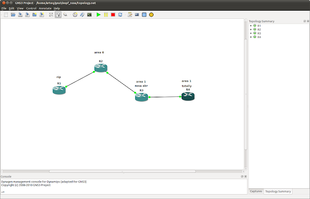
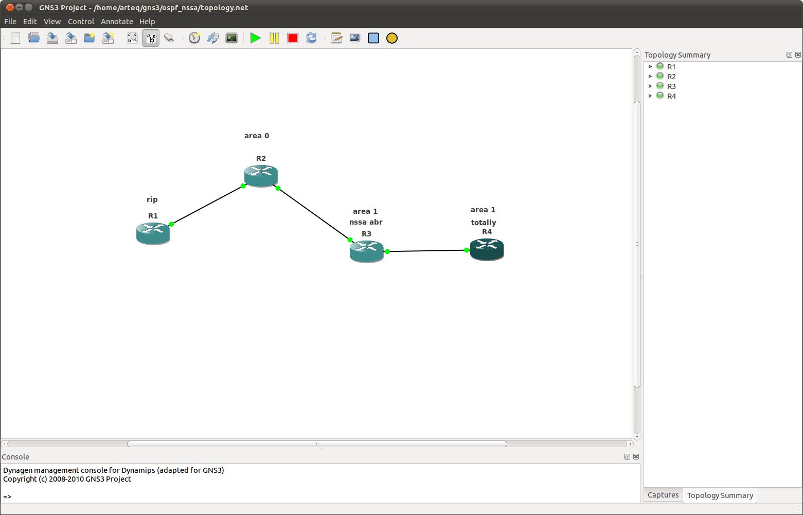
basic... rip and ospf haven't been redistributed yet, and nssa is not yet in effect...
r4#sh ip ospf data
OSPF Router with ID (4.4.4.4) (Process ID 1)
Router Link States (Area 1)
Link ID ADV Router Age Seq# Checksum Link count
2.2.2.2 2.2.2.2 444 0x80000002 0x0061A3 1
3.3.3.3 3.3.3.3 240 0x80000005 0x009413 3
4.4.4.4 4.4.4.4 229 0x80000003 0x00F5D4 2
Net Link States (Area 1)
Link ID ADV Router Age Seq# Checksum
10.1.2.1 2.2.2.2 444 0x80000001 0x008F80
10.1.4.3 3.3.3.3 240 0x80000001 0x009B64
Summary Net Link States (Area 1)
Link ID ADV Router Age Seq# Checksum
2.2.2.2 2.2.2.2 586 0x80000001 0x00FA31
10.1.1.0 2.2.2.2 606 0x80000001 0x00BD6A
r4#
lsa types 1,2 and 3 are represented on r4, as expected...

we'll first redist rip and ospf...
r4#sh ip ospf data
OSPF Router with ID (4.4.4.4) (Process ID 1)
Router Link States (Area 1)
Link ID ADV Router Age Seq# Checksum Link count
2.2.2.2 2.2.2.2 41 0x80000005 0x00619E 1
3.3.3.3 3.3.3.3 1359 0x80000005 0x009413 3
4.4.4.4 4.4.4.4 67 0x80000005 0x00F1D6 2
Net Link States (Area 1)
Link ID ADV Router Age Seq# Checksum
10.1.2.1 2.2.2.2 1562 0x80000001 0x008F80
10.1.4.3 3.3.3.3 1358 0x80000001 0x009B64
Summary Net Link States (Area 1)
Link ID ADV Router Age Seq# Checksum
2.2.2.2 2.2.2.2 1704 0x80000001 0x00FA31
10.1.1.0 2.2.2.2 1724 0x80000001 0x00BD6A
Type-5 AS External Link States
Link ID ADV Router Age Seq# Checksum Tag
1.0.0.0 2.2.2.2 40 0x80000001 0x003456 0
r4#
now we have the expected external type on r4...
and for completeness, rip has picked up some new friends...
rip#sh ip route rip
Gateway of last resort is not set
R 2.0.0.0/8 [120/5] via 10.1.1.2, 00:00:27, FastEthernet0/0
R 3.0.0.0/8 [120/5] via 10.1.1.2, 00:00:27, FastEthernet0/0
R 4.0.0.0/8 [120/5] via 10.1.1.2, 00:00:27, FastEthernet0/0
10.0.0.0/8 is variably subnetted, 4 subnets, 2 masks
R 10.1.2.0/24 [120/1] via 10.1.1.2, 00:00:27, FastEthernet0/0
R 10.1.4.0/24 [120/5] via 10.1.1.2, 00:00:27, FastEthernet0/0
back to stubs...
to make area 1 a stub include the abr (in this case the bb or r1) and r3... the rule is that all routers in stub areas participate in being stubs... in other words, if we simply made r3 a stub, it would lose it's adjacency...
Area 1
Number of interfaces in this area is 1
It is a stub area
r3 has it's adjacency to r1 but no longer has type 5's...
r3#sh ip ospf data
OSPF Router with ID (3.3.3.3) (Process ID 1)
Router Link States (Area 1)
Link ID ADV Router Age Seq# Checksum Link count
2.2.2.2 2.2.2.2 533 0x80000007 0x008976 1
3.3.3.3 3.3.3.3 532 0x80000008 0x0018A0 3
4.4.4.4 4.4.4.4 1273 0x80000005 0x00F1D6 2
Net Link States (Area 1)
Link ID ADV Router Age Seq# Checksum
10.1.2.3 3.3.3.3 532 0x80000001 0x006BA0
Summary Net Link States (Area 1)
Link ID ADV Router Age Seq# Checksum
0.0.0.0 2.2.2.2 537 0x80000001 0x0075C0
2.2.2.2 2.2.2.2 537 0x80000003 0x001517
10.1.1.0 2.2.2.2 537 0x80000003 0x00D750
make area 1 totally stubby by adding no-summary to r2...
on r2 sh ip ospf:
Area 1
Number of interfaces in this area is 1
It is a stub area, no summary LSA in this area
Generates stub default route with cost 1
r3#sh ip ospf data
OSPF Router with ID (3.3.3.3) (Process ID 1)
Router Link States (Area 1)
Link ID ADV Router Age Seq# Checksum Link count
2.2.2.2 2.2.2.2 847 0x80000007 0x008976 1
3.3.3.3 3.3.3.3 846 0x80000008 0x0018A0 3
4.4.4.4 4.4.4.4 1587 0x80000005 0x00F1D6 2
Net Link States (Area 1)
Link ID ADV Router Age Seq# Checksum
10.1.2.3 3.3.3.3 846 0x80000001 0x006BA0
Summary Net Link States (Area 1)
Link ID ADV Router Age Seq# Checksum
0.0.0.0 2.2.2.2 163 0x80000003 0x0071C2
change to nssa on r2 and r3 and we have:
r3#sh ip ospf data
OSPF Router with ID (3.3.3.3) (Process ID 1)
Router Link States (Area 1)
Link ID ADV Router Age Seq# Checksum Link count
2.2.2.2 2.2.2.2 21 0x8000000B 0x000FE2 1
3.3.3.3 3.3.3.3 20 0x8000000C 0x009715 3
4.4.4.4 4.4.4.4 95 0x80000007 0x0004C1 2
Net Link States (Area 1)
Link ID ADV Router Age Seq# Checksum
10.1.2.3 3.3.3.3 15 0x80000005 0x00EA15
10.1.4.4 4.4.4.4 95 0x80000001 0x006397
Summary Net Link States (Area 1)
Link ID ADV Router Age Seq# Checksum
2.2.2.2 2.2.2.2 22 0x80000004 0x009A88
10.1.1.0 2.2.2.2 22 0x80000004 0x005DC1
Type-7 AS External Link States (Area 1)
Link ID ADV Router Age Seq# Checksum Tag
1.0.0.0 2.2.2.2 21 0x80000001 0x008213 0
just like in the stub scenario, r4 will have to become an nssa also to particpate... all routers in the area...
r4(config-router)#no area 1 nssa
r4(config-router)#
*Nov 25 14:40:10.931: %OSPF-5-ADJCHG: Process 1, Nbr 3.3.3.3 on FastEthernet0/0 from FULL to DOWN, Neighbor Down: Adjacency forced to reset
add area 1 nssa no-summary to r2 and:
r3#sh ip ospf data
OSPF Router with ID (3.3.3.3) (Process ID 1)
Router Link States (Area 1)
Link ID ADV Router Age Seq# Checksum Link count
2.2.2.2 2.2.2.2 186 0x8000000C 0x000DE3 1
3.3.3.3 3.3.3.3 96 0x80000010 0x007E15 3
4.4.4.4 4.4.4.4 97 0x8000000B 0x00A11A 2
Net Link States (Area 1)
Link ID ADV Router Age Seq# Checksum
10.1.2.3 3.3.3.3 544 0x80000005 0x00EA15
10.1.4.4 4.4.4.4 93 0x80000005 0x0001EF
Summary Net Link States (Area 1)
Link ID ADV Router Age Seq# Checksum
0.0.0.0 2.2.2.2 14 0x80000001 0x00FC31
Type-7 AS External Link States (Area 1)
Link ID ADV Router Age Seq# Checksum Tag
1.0.0.0 2.2.2.2 550 0x80000001 0x008213 0
on r2:
Area 1
Number of interfaces in this area is 1
It is a NSSA area
Perform type-7/type-5 LSA translation
basic... rip and ospf haven't been redistributed yet, and nssa is not yet in effect...
r4#sh ip ospf data
OSPF Router with ID (4.4.4.4) (Process ID 1)
Router Link States (Area 1)
Link ID ADV Router Age Seq# Checksum Link count
2.2.2.2 2.2.2.2 444 0x80000002 0x0061A3 1
3.3.3.3 3.3.3.3 240 0x80000005 0x009413 3
4.4.4.4 4.4.4.4 229 0x80000003 0x00F5D4 2
Net Link States (Area 1)
Link ID ADV Router Age Seq# Checksum
10.1.2.1 2.2.2.2 444 0x80000001 0x008F80
10.1.4.3 3.3.3.3 240 0x80000001 0x009B64
Summary Net Link States (Area 1)
Link ID ADV Router Age Seq# Checksum
2.2.2.2 2.2.2.2 586 0x80000001 0x00FA31
10.1.1.0 2.2.2.2 606 0x80000001 0x00BD6A
r4#
lsa types 1,2 and 3 are represented on r4, as expected...

we'll first redist rip and ospf...
r4#sh ip ospf data
OSPF Router with ID (4.4.4.4) (Process ID 1)
Router Link States (Area 1)
Link ID ADV Router Age Seq# Checksum Link count
2.2.2.2 2.2.2.2 41 0x80000005 0x00619E 1
3.3.3.3 3.3.3.3 1359 0x80000005 0x009413 3
4.4.4.4 4.4.4.4 67 0x80000005 0x00F1D6 2
Net Link States (Area 1)
Link ID ADV Router Age Seq# Checksum
10.1.2.1 2.2.2.2 1562 0x80000001 0x008F80
10.1.4.3 3.3.3.3 1358 0x80000001 0x009B64
Summary Net Link States (Area 1)
Link ID ADV Router Age Seq# Checksum
2.2.2.2 2.2.2.2 1704 0x80000001 0x00FA31
10.1.1.0 2.2.2.2 1724 0x80000001 0x00BD6A
Type-5 AS External Link States
Link ID ADV Router Age Seq# Checksum Tag
1.0.0.0 2.2.2.2 40 0x80000001 0x003456 0
r4#
now we have the expected external type on r4...
and for completeness, rip has picked up some new friends...
rip#sh ip route rip
Gateway of last resort is not set
R 2.0.0.0/8 [120/5] via 10.1.1.2, 00:00:27, FastEthernet0/0
R 3.0.0.0/8 [120/5] via 10.1.1.2, 00:00:27, FastEthernet0/0
R 4.0.0.0/8 [120/5] via 10.1.1.2, 00:00:27, FastEthernet0/0
10.0.0.0/8 is variably subnetted, 4 subnets, 2 masks
R 10.1.2.0/24 [120/1] via 10.1.1.2, 00:00:27, FastEthernet0/0
R 10.1.4.0/24 [120/5] via 10.1.1.2, 00:00:27, FastEthernet0/0
back to stubs...
to make area 1 a stub include the abr (in this case the bb or r1) and r3... the rule is that all routers in stub areas participate in being stubs... in other words, if we simply made r3 a stub, it would lose it's adjacency...
r2#sh ip ospf
omittedArea 1
Number of interfaces in this area is 1
It is a stub area
r3 has it's adjacency to r1 but no longer has type 5's...
r3#sh ip ospf data
OSPF Router with ID (3.3.3.3) (Process ID 1)
Router Link States (Area 1)
Link ID ADV Router Age Seq# Checksum Link count
2.2.2.2 2.2.2.2 533 0x80000007 0x008976 1
3.3.3.3 3.3.3.3 532 0x80000008 0x0018A0 3
4.4.4.4 4.4.4.4 1273 0x80000005 0x00F1D6 2
Net Link States (Area 1)
Link ID ADV Router Age Seq# Checksum
10.1.2.3 3.3.3.3 532 0x80000001 0x006BA0
Summary Net Link States (Area 1)
Link ID ADV Router Age Seq# Checksum
0.0.0.0 2.2.2.2 537 0x80000001 0x0075C0
2.2.2.2 2.2.2.2 537 0x80000003 0x001517
10.1.1.0 2.2.2.2 537 0x80000003 0x00D750
make area 1 totally stubby by adding no-summary to r2...
on r2 sh ip ospf:
Area 1
Number of interfaces in this area is 1
It is a stub area, no summary LSA in this area
Generates stub default route with cost 1
r3#sh ip ospf data
OSPF Router with ID (3.3.3.3) (Process ID 1)
Router Link States (Area 1)
Link ID ADV Router Age Seq# Checksum Link count
2.2.2.2 2.2.2.2 847 0x80000007 0x008976 1
3.3.3.3 3.3.3.3 846 0x80000008 0x0018A0 3
4.4.4.4 4.4.4.4 1587 0x80000005 0x00F1D6 2
Net Link States (Area 1)
Link ID ADV Router Age Seq# Checksum
10.1.2.3 3.3.3.3 846 0x80000001 0x006BA0
Summary Net Link States (Area 1)
Link ID ADV Router Age Seq# Checksum
0.0.0.0 2.2.2.2 163 0x80000003 0x0071C2
change to nssa on r2 and r3 and we have:
r3#sh ip ospf data
OSPF Router with ID (3.3.3.3) (Process ID 1)
Router Link States (Area 1)
Link ID ADV Router Age Seq# Checksum Link count
2.2.2.2 2.2.2.2 21 0x8000000B 0x000FE2 1
3.3.3.3 3.3.3.3 20 0x8000000C 0x009715 3
4.4.4.4 4.4.4.4 95 0x80000007 0x0004C1 2
Net Link States (Area 1)
Link ID ADV Router Age Seq# Checksum
10.1.2.3 3.3.3.3 15 0x80000005 0x00EA15
10.1.4.4 4.4.4.4 95 0x80000001 0x006397
Summary Net Link States (Area 1)
Link ID ADV Router Age Seq# Checksum
2.2.2.2 2.2.2.2 22 0x80000004 0x009A88
10.1.1.0 2.2.2.2 22 0x80000004 0x005DC1
Type-7 AS External Link States (Area 1)
Link ID ADV Router Age Seq# Checksum Tag
1.0.0.0 2.2.2.2 21 0x80000001 0x008213 0
just like in the stub scenario, r4 will have to become an nssa also to particpate... all routers in the area...
r4(config-router)#no area 1 nssa
r4(config-router)#
*Nov 25 14:40:10.931: %OSPF-5-ADJCHG: Process 1, Nbr 3.3.3.3 on FastEthernet0/0 from FULL to DOWN, Neighbor Down: Adjacency forced to reset
add area 1 nssa no-summary to r2 and:
r3#sh ip ospf data
OSPF Router with ID (3.3.3.3) (Process ID 1)
Router Link States (Area 1)
Link ID ADV Router Age Seq# Checksum Link count
2.2.2.2 2.2.2.2 186 0x8000000C 0x000DE3 1
3.3.3.3 3.3.3.3 96 0x80000010 0x007E15 3
4.4.4.4 4.4.4.4 97 0x8000000B 0x00A11A 2
Net Link States (Area 1)
Link ID ADV Router Age Seq# Checksum
10.1.2.3 3.3.3.3 544 0x80000005 0x00EA15
10.1.4.4 4.4.4.4 93 0x80000005 0x0001EF
Summary Net Link States (Area 1)
Link ID ADV Router Age Seq# Checksum
0.0.0.0 2.2.2.2 14 0x80000001 0x00FC31
Type-7 AS External Link States (Area 1)
Link ID ADV Router Age Seq# Checksum Tag
1.0.0.0 2.2.2.2 550 0x80000001 0x008213 0
on r2:
Area 1
Number of interfaces in this area is 1
It is a NSSA area
Perform type-7/type-5 LSA translation
area types and lsa's...
all area types will have type 1 and 2 lsa's
bb and standard will also have 3,4,5 but no type 7 (nssa)
stub will have 1,2 and 3 while totally stubby can have only 1 and 2 (no summary)
nssa will have 1,2 and 3 and also type 7; totally nssa is similar to totally stubby (can you say totally) in that type 3 summary is not allowed but type 7 (nssa) still is... only the nssa types support type 7...
the overwhelming difference with the stubs is their treatment of abr summary and external routes... the stub types never support type 4 (asbr summary) or 5 (external)...
nssa supports external routes (type 5) in that they are interpreted as type 7 on the way in and out of the nssa area by the nssa abr...
don't believe me; here is how cisco puts it:
http://www.cisco.com/en/US/tech/tk365/technologies_tech_note09186a0080094a88.shtml#topic1
The OSPF not-so-stubby area (NSSA) feature is described by RFC 1587 and is first introduced in Cisco IOS®
Software release 11.2. It is a non-proprietary extension of the
existing stub area feature that allows the injection of external routes
in a limited fashion into the stub area.
and is first introduced in Cisco IOS®
Software release 11.2. It is a non-proprietary extension of the
existing stub area feature that allows the injection of external routes
in a limited fashion into the stub area.
Redistribution into an NSSA area creates a special type of link-state advertisement (LSA) known as type 7, which can only exist in an NSSA area. An NSSA autonomous system boundary router (ASBR) generates this LSA and an NSSA area border router (ABR) translates it into a type 5 LSA, which gets propagated into the OSPF domain.
and further:
This is a type 7 LSA that is generated by an NSSA ASBR. Type 5 LSAs are not allowed in NSSA areas, so the NSSA ASBR generates a type 7 LSA instead, which remains within the NSSA. This type 7 LSA gets translated back into a type 5 by the NSSA ABR.
bb and standard will also have 3,4,5 but no type 7 (nssa)
stub will have 1,2 and 3 while totally stubby can have only 1 and 2 (no summary)
nssa will have 1,2 and 3 and also type 7; totally nssa is similar to totally stubby (can you say totally) in that type 3 summary is not allowed but type 7 (nssa) still is... only the nssa types support type 7...
the overwhelming difference with the stubs is their treatment of abr summary and external routes... the stub types never support type 4 (asbr summary) or 5 (external)...
nssa supports external routes (type 5) in that they are interpreted as type 7 on the way in and out of the nssa area by the nssa abr...
don't believe me; here is how cisco puts it:
http://www.cisco.com/en/US/tech/tk365/technologies_tech_note09186a0080094a88.shtml#topic1
The OSPF not-so-stubby area (NSSA) feature is described by RFC 1587
Redistribution into an NSSA area creates a special type of link-state advertisement (LSA) known as type 7, which can only exist in an NSSA area. An NSSA autonomous system boundary router (ASBR) generates this LSA and an NSSA area border router (ABR) translates it into a type 5 LSA, which gets propagated into the OSPF domain.
and further:
This is a type 7 LSA that is generated by an NSSA ASBR. Type 5 LSAs are not allowed in NSSA areas, so the NSSA ASBR generates a type 7 LSA instead, which remains within the NSSA. This type 7 LSA gets translated back into a type 5 by the NSSA ABR.
just because...
i love this schematic... ipv4 v ipv6 encore...

while the above are representative of a packet header, below is representative of a packet rearer...

kim k's hips thighs and buttocks... and i thought the ccie syllabutt was big...
while the above are representative of a packet header, below is representative of a packet rearer...

kim k's hips thighs and buttocks... and i thought the ccie syllabutt was big...
Saturday, November 24, 2012
classless, cidr and vlsm...
i often read people misrepresenting these three ideas, or grouping them together as if they all mean the same thing...
CIDR was created to help avoid depletion of the ipv4 space, and specifically to conserve class B addresses in the internet... CIDR is actually a grouping together of subnets, or supernetting large quantities of aggregatable addresses...
VLSM is subnetting, or the dividing up of addresses into ranges whereby overlapping is avoided and essentially, smaller, more manageable and efficient networks are created from larger ones...
Classless means the extrication of address space from classful boundaries, ie, from classful subnet masks as in /8, /16 and /24...
your seed...
Protocol Default Seed Metric
OSPF 20; except BGP, which is 1
IS-IS 0
RIP Infinity
IGRP/EIGRP Infinity
the seed metric is normally governed by a router's interface, however, with redistribution the routes are not connected to the interface, hence the need for seed... infinity dictates that a seed metric is required...
OSPF 20; except BGP, which is 1
IS-IS 0
RIP Infinity
IGRP/EIGRP Infinity
the seed metric is normally governed by a router's interface, however, with redistribution the routes are not connected to the interface, hence the need for seed... infinity dictates that a seed metric is required...
Monday, November 19, 2012
ospf states...
according to rfc 2328... (abridged)
Down
            This is the initial state of a neighbor conversation.  It
            indicates that there has been no recent information received
            from the neighbor.
Attempt
            This state is only valid for neighbors attached to NBMA
            networks.  It indicates that no recent information has been
            received from the neighbor, but that a more concerted effort
            should be made to contact the neighbor.  This is done by
            sending the neighbor Hello packets at intervals of
            HelloInterval
Init
            In this state, an Hello packet has recently been seen from
            the neighbor.  However, bidirectional communication has not
            yet been established with the neighbor (i.e., the router
            itself did not appear in the neighbor's Hello packet).  All
            neighbors in this state (or higher) are listed in the Hello
            packets sent from the associated interface.
2-Way
            In this state, communication between the two routers is
            bidirectional.  This has been assured by the operation of
            the Hello Protocol.  This is the most advanced state short
            of beginning adjacency establishment.  The (Backup)
            Designated Router is selected from the set of neighbors in
            state 2-Way or greater.

ExStart
            This is the first step in creating an adjacency between the
            two neighboring routers.  The goal of this step is to decide
            which router is the master, and to decide upon the initial
            DD sequence number.  Neighbor conversations in this state or
            greater are called adjacencies.

Exchange
            In this state the router is describing its entire link state
            database by sending Database Description packets to the
            neighbor.  Each Database Description Packet has a DD
            sequence number, and is explicitly acknowledged.  Only one
            Database Description Packet is allowed outstanding at any
            one time.  In this state, Link State Request Packets may
            also be sent asking for the neighbor's more recent LSAs.
            All adjacencies in Exchange state or greater are used by the
            flooding procedure.  In fact, these adjacencies are fully
            capable of transmitting and receiving all types of OSPF
            routing protocol packets.

Loading
            In this state, Link State Request packets are sent to the
            neighbor asking for the more recent LSAs that have been
            discovered (but not yet received) in the Exchange state.

Full
            In this state, the neighboring routers are fully adjacent.
            These adjacencies will now appear in router-LSAs and
            network-LSAs.
from cisco.com:
2-Way
  This state designates that bi-directional communication has been
  established between two routers. Bi-directional means that each router has seen
  the other's hello packet. This state is attained when the router receiving the
  hello packet sees its own Router ID within the received hello packet's neighbor
  field. At this state, a router decides whether to become adjacent with this
  neighbor. On broadcast media and non-broadcast multiaccess networks, a router
  becomes full only with the designated router (DR) and the backup designated router
  (BDR); it stays in the 2-way state with all  other neighbors. On Point-to-point and
   Point-to-multipoint networks, a router becomes full with all connected routers.
 At the end of this stage, the DR and BDR for broadcast and
  non-broadcast multiacess networks are elected. For more information on the DR
  election process, refer to DR   Election.

Note: Receiving a Database Descriptor (DBD) packet from a neighbor in the
  init state will also a cause a transition to 2-way state.
Sunday, November 18, 2012
quote of the day part 2...
legendary scott morris has been quoted, in reference to the ccie lab exam:
"don't look at the CCIE as several $1500 exams - look at it as a $4500 exam, and if you pass early, you get a discount!"
either way, that's a lot of bread...
"don't look at the CCIE as several $1500 exams - look at it as a $4500 exam, and if you pass early, you get a discount!"
either way, that's a lot of bread...
arden ospf filters, take 3....
nice database...
R5#sh ip ospf data
OSPF Router with ID (5.5.5.5) (Process ID 1)
Router Link States (Area 1)
Link ID ADV Router Age Seq# Checksum Link count
3.3.3.3 3.3.3.3 1646 0x80000004 0x001133 2
4.4.4.4 4.4.4.4 1611 0x80000003 0x0037CE 3
5.5.5.5 5.5.5.5 1609 0x80000005 0x008F64 3
Net Link States (Area 1)
Link ID ADV Router Age Seq# Checksum
10.1.34.3 3.3.3.3 1712 0x80000001 0x005091
10.1.35.3 3.3.3.3 1646 0x80000001 0x007765
10.1.45.4 4.4.4.4 1610 0x80000001 0x0003C6
Summary Net Link States (Area 1)
Link ID ADV Router Age Seq# Checksum
1.1.1.1 3.3.3.3 1769 0x80000001 0x001516
2.2.2.2 3.3.3.3 1769 0x80000001 0x00E640
3.3.3.3 3.3.3.3 1769 0x80000001 0x00AE75
10.0.12.0 3.3.3.3 1769 0x80000001 0x003CDC
10.0.13.0 3.3.3.3 1769 0x80000001 0x0027F1
10.0.23.0 3.3.3.3 1769 0x80000001 0x00B856
R5#
permit the 3.3.3.3 route...
the implicit deny all, in action... this is very exciting... he goes on to explain that the database has not been changed by our distribute-list...
the upshot...
So the distribute-list command doesn’t affect routes as they enter or leave the OSPF topology database. The distribute-list command affects routes as they go in and out of the routing table. It does not prevent link state packets from being propagated.
R5#sh ip ospf data
OSPF Router with ID (5.5.5.5) (Process ID 1)
Router Link States (Area 1)
Link ID ADV Router Age Seq# Checksum Link count
3.3.3.3 3.3.3.3 133 0x80000005 0x000F34 2
4.4.4.4 4.4.4.4 31 0x80000004 0x0035CF 3
5.5.5.5 5.5.5.5 1902 0x80000005 0x008F64 3
Net Link States (Area 1)
Link ID ADV Router Age Seq# Checksum
10.1.34.3 3.3.3.3 133 0x80000002 0x004E92
10.1.35.3 3.3.3.3 133 0x80000002 0x007566
10.1.45.4 4.4.4.4 31 0x80000002 0x0001C7
Summary Net Link States (Area 1)
Link ID ADV Router Age Seq# Checksum
1.1.1.1 3.3.3.3 133 0x80000002 0x001317
2.2.2.2 3.3.3.3 133 0x80000002 0x00E441
3.3.3.3 3.3.3.3 133 0x80000002 0x00AC76
10.0.12.0 3.3.3.3 133 0x80000002 0x003ADD
10.0.13.0 3.3.3.3 133 0x80000002 0x0025F2
10.0.23.0 3.3.3.3 133 0x80000002 0x00B657
R5#sh ip ospf data
OSPF Router with ID (5.5.5.5) (Process ID 1)
Router Link States (Area 1)
Link ID ADV Router Age Seq# Checksum Link count
3.3.3.3 3.3.3.3 1646 0x80000004 0x001133 2
4.4.4.4 4.4.4.4 1611 0x80000003 0x0037CE 3
5.5.5.5 5.5.5.5 1609 0x80000005 0x008F64 3
Net Link States (Area 1)
Link ID ADV Router Age Seq# Checksum
10.1.34.3 3.3.3.3 1712 0x80000001 0x005091
10.1.35.3 3.3.3.3 1646 0x80000001 0x007765
10.1.45.4 4.4.4.4 1610 0x80000001 0x0003C6
Summary Net Link States (Area 1)
Link ID ADV Router Age Seq# Checksum
1.1.1.1 3.3.3.3 1769 0x80000001 0x001516
2.2.2.2 3.3.3.3 1769 0x80000001 0x00E640
3.3.3.3 3.3.3.3 1769 0x80000001 0x00AE75
10.0.12.0 3.3.3.3 1769 0x80000001 0x003CDC
10.0.13.0 3.3.3.3 1769 0x80000001 0x0027F1
10.0.23.0 3.3.3.3 1769 0x80000001 0x00B856
R5#
permit the 3.3.3.3 route...
R5#config t
Enter configuration commands, one per line. End with CNTL/Z.
R5(config)#access-list 1 permit 3.3.3.3
R5(config)#router ospf 1
R5(config-router)#distribute-list 1 in
R5(config-router)#end
R5#
*Nov 18 12:34:29.983: %SYS-5-CONFIG_I: Configured from console by console
Enter configuration commands, one per line. End with CNTL/Z.
R5(config)#access-list 1 permit 3.3.3.3
R5(config)#router ospf 1
R5(config-router)#distribute-list 1 in
R5(config-router)#end
R5#
*Nov 18 12:34:29.983: %SYS-5-CONFIG_I: Configured from console by console
R5#sh ip route | excl L | incl loop
Gateway of last resort is not set
3.0.0.0/32 is subnetted, 1 subnets
O IA 3.3.3.3 [110/2] via 10.1.35.3, 00:00:18, FastEthernet1/0
5.0.0.0/32 is subnetted, 1 subnets
C 5.5.5.5 is directly connected, Loopback0
10.0.0.0/8 is variably subnetted, 4 subnets, 2 masks
C 10.1.35.0/24 is directly connected, FastEthernet1/0
C 10.1.45.0/24 is directly connected, FastEthernet1/1
the implicit deny all, in action... this is very exciting... he goes on to explain that the database has not been changed by our distribute-list...
the upshot...
So the distribute-list command doesn’t affect routes as they enter or leave the OSPF topology database. The distribute-list command affects routes as they go in and out of the routing table. It does not prevent link state packets from being propagated.
R5#sh ip ospf data
OSPF Router with ID (5.5.5.5) (Process ID 1)
Router Link States (Area 1)
Link ID ADV Router Age Seq# Checksum Link count
3.3.3.3 3.3.3.3 133 0x80000005 0x000F34 2
4.4.4.4 4.4.4.4 31 0x80000004 0x0035CF 3
5.5.5.5 5.5.5.5 1902 0x80000005 0x008F64 3
Net Link States (Area 1)
Link ID ADV Router Age Seq# Checksum
10.1.34.3 3.3.3.3 133 0x80000002 0x004E92
10.1.35.3 3.3.3.3 133 0x80000002 0x007566
10.1.45.4 4.4.4.4 31 0x80000002 0x0001C7
Summary Net Link States (Area 1)
Link ID ADV Router Age Seq# Checksum
1.1.1.1 3.3.3.3 133 0x80000002 0x001317
2.2.2.2 3.3.3.3 133 0x80000002 0x00E441
3.3.3.3 3.3.3.3 133 0x80000002 0x00AC76
10.0.12.0 3.3.3.3 133 0x80000002 0x003ADD
10.0.13.0 3.3.3.3 133 0x80000002 0x0025F2
10.0.23.0 3.3.3.3 133 0x80000002 0x00B657
arden's ospf filters II...
don't hate me because my topology is beautiful...

my route table:
R5#sh ip route | excl L | incl loop
Gateway of last resort is not set
1.0.0.0/32 is subnetted, 1 subnets
O IA 1.1.1.1 [110/3] via 10.1.35.3, 00:20:01, FastEthernet1/0
2.0.0.0/32 is subnetted, 1 subnets
O IA 2.2.2.2 [110/3] via 10.1.35.3, 00:20:01, FastEthernet1/0
3.0.0.0/32 is subnetted, 1 subnets
O IA 3.3.3.3 [110/2] via 10.1.35.3, 00:20:01, FastEthernet1/0
4.0.0.0/32 is subnetted, 1 subnets
O 4.4.4.4 [110/2] via 10.1.45.4, 00:19:26, FastEthernet1/1
5.0.0.0/32 is subnetted, 1 subnets
C 5.5.5.5 is directly connected, Loopback0
10.0.0.0/8 is variably subnetted, 8 subnets, 2 masks
O IA 10.0.12.0/24 [110/3] via 10.1.35.3, 00:20:01, FastEthernet1/0
O IA 10.0.13.0/24 [110/2] via 10.1.35.3, 00:20:01, FastEthernet1/0
O IA 10.0.23.0/24 [110/2] via 10.1.35.3, 00:20:01, FastEthernet1/0
O 10.1.34.0/24 [110/2] via 10.1.45.4, 00:19:26, FastEthernet1/1
[110/2] via 10.1.35.3, 00:20:01, FastEthernet1/0
C 10.1.35.0/24 is directly connected, FastEthernet1/0
C 10.1.45.0/24 is directly connected, FastEthernet1/1
and arden's...
R5#sh ip route | b GatewayGateway of last resort is not set |
1.0.0.0/32 is subnetted, 1 subnets |
O IA 1.1.1.1 [110/21] via 10.1.35.3, 00:47:50, Ethernet1/0 |
2.0.0.0/32 is subnetted, 1 subnets |
O IA 2.2.2.2 [110/21] via 10.1.35.3, 00:47:50, Ethernet1/0 |
3.0.0.0/32 is subnetted, 1 subnets |
O IA 3.3.3.3 [110/11] via 10.1.35.3, 00:47:50, Ethernet1/0 |
4.0.0.0/32 is subnetted, 1 subnets |
O 4.4.4.4 [110/11] via 10.1.45.4, 00:47:50, Ethernet1/1 |
5.0.0.0/32 is subnetted, 1 subnets |
C 5.5.5.5 is directly connected, Loopback0 |
10.0.0.0/24 is subnetted, 6 subnets |
O IA 10.0.12.0 [110/30] via 10.1.35.3, 00:47:50, Ethernet1/0 |
O IA 10.0.13.0 [110/20] via 10.1.35.3, 00:47:50, Ethernet1/0 |
O IA 10.0.23.0 [110/20] via 10.1.35.3, 00:47:50, Ethernet1/0 |
C 10.1.45.0 is directly connected, Ethernet1/1 |
C 10.1.35.0 is directly connected, Ethernet1/0 |
O 10.1.34.0 [110/20] via 10.1.45.4, 00:47:50, Ethernet1/1 |
[110/20] via 10.1.35.3, 00:47:50, Ethernet1/0 | | | | | |
arden's ospf filter tutorial...
because i was in the mood for a change up, and i like this guy's style...
http://ardenpackeer.com/tutorials/routeswitch/tutorial-filtering-routes-in-ospf-part-1-filtering-within-an-area/
and this is a gift from me to you... all set with 7200's (i can't stand 3640's)... you know the adjustments to make to the .net... turn to... i even added the no shuts to the configs for you... the holidays and all...
autostart = False
[127.0.0.1:7200]
workingdir = working
udp = 10000
[[7200]]
image = /home/arteq/ios/c7200-adventerprisek9-mz.152-4.S.image
idlepc = 0x62ef0d90
ghostios = True
[[ROUTER R4]]
console = 2003
slot0 = C7200-IO-2FE
slot1 = PA-2FE-TX
f1/0 = R3 f2/0
f1/1 = R5 f1/1
cnfg = configs/R4.cfg
x = 51.0
y = -241.0
[[ROUTER R1]]
console = 2000
slot0 = C7200-IO-2FE
slot1 = PA-2FE-TX
f1/0 = R3 f1/0
f1/1 = R2 f1/1
cnfg = configs/R1.cfg
x = -379.0
y = -222.0
[[ROUTER R2]]
console = 2001
slot0 = C7200-IO-2FE
slot1 = PA-2FE-TX
f1/0 = R3 f1/1
f1/1 = R1 f1/1
cnfg = configs/R2.cfg
x = -377.0
y = -8.0
[[ROUTER R3]]
console = 2002
slot0 = C7200-IO-2FE
slot1 = PA-2FE-TX
f1/0 = R1 f1/0
f1/1 = R2 f1/0
slot2 = PA-2FE-TX
f2/0 = R4 f1/0
f2/1 = R5 f1/0
cnfg = configs/R3.cfg
x = -164.0
y = -127.0
[127.0.0.1:7201]
workingdir = working
udp = 10100
[[7200]]
image = /home/arteq/ios/c7200-adventerprisek9-mz.152-4.S.image
idlepc = 0x62ef0d90
ghostios = True
[[ROUTER R5]]
console = 2004
slot0 = C7200-IO-2FE
slot1 = PA-2FE-TX
f1/0 = R3 f2/1
f1/1 = R4 f1/1
cnfg = configs/R5.cfg
x = 57.0
y = -10.0
[GNS3-DATA]
configs = configs
workdir = working
and the configs...
hostname R1
!
interface Loopback0
ip address 1.1.1.1 255.255.255.255
!
interface f1/0
ip address 10.0.13.1 255.255.255.0
full-duplex
no shut
!
interface f1/1
ip address 10.0.12.1 255.255.255.0
full-duplex
no shut
!
router ospf 1
router-id 1.1.1.1
log-adjacency-changes
network 1.1.1.1 0.0.0.0 area 0
network 10.0.12.1 0.0.0.0 area 0
network 10.0.13.1 0.0.0.0 area 0
hostname R2
!
interface Loopback0
ip address 2.2.2.2 255.255.255.255
!
interface f1/0
ip address 10.0.23.2 255.255.255.0
full-duplex
no shut
!
interface f1/1
ip address 10.0.12.2 255.255.255.0
full-duplex
no shut
!
router ospf 1
router-id 2.2.2.2
log-adjacency-changes
network 2.2.2.2 0.0.0.0 area 0
network 10.0.12.2 0.0.0.0 area 0
network 10.0.23.2 0.0.0.0 area 0
hostname R3
!
interface Loopback0
ip address 3.3.3.3 255.255.255.255
!
interface f1/0
ip address 10.0.13.3 255.255.255.0
full-duplex
no shut
!
interface f1/1
ip address 10.0.23.3 255.255.255.0
full-duplex
no shut
!
interface f2/0
ip address 10.1.34.3 255.255.255.0
full-duplex
no shut
!
interface f2/1
ip address 10.1.35.3 255.255.255.0
full-duplex
no shut
!
router ospf 1
router-id 3.3.3.3
log-adjacency-changes
network 3.3.3.3 0.0.0.0 area 0
network 10.0.13.3 0.0.0.0 area 0
network 10.0.23.3 0.0.0.0 area 0
network 10.1.34.3 0.0.0.0 area 1
network 10.1.35.3 0.0.0.0 area 1
hostname R4
!
interface Loopback0
ip address 4.4.4.4 255.255.255.255
!
interface f1/0
ip address 10.1.34.4 255.255.255.0
full-duplex
no shut
!
interface f1/1
ip address 10.1.45.4 255.255.255.0
full-duplex
no shut
!
router ospf 1
router-id 4.4.4.4
log-adjacency-changes
network 4.4.4.4 0.0.0.0 area 1
network 10.1.34.4 0.0.0.0 area 1
network 10.1.45.4 0.0.0.0 area 1
hostname R5
!
interface Loopback0
ip address 5.5.5.5 255.255.255.255
!
interface f1/0
ip address 10.1.35.5 255.255.255.0
full-duplex
no shut
!
interface f1/1
ip address 10.1.45.5 255.255.255.0
full-duplex
no shut
!
router ospf 1
router-id 5.5.5.5
log-adjacency-changes
network 5.5.5.5 0.0.0.0 area 1
network 10.1.35.5 0.0.0.0 area 1
network 10.1.45.5 0.0.0.0 area 1
http://ardenpackeer.com/tutorials/routeswitch/tutorial-filtering-routes-in-ospf-part-1-filtering-within-an-area/

and this is a gift from me to you... all set with 7200's (i can't stand 3640's)... you know the adjustments to make to the .net... turn to... i even added the no shuts to the configs for you... the holidays and all...
autostart = False
[127.0.0.1:7200]
workingdir = working
udp = 10000
[[7200]]
image = /home/arteq/ios/c7200-adventerprisek9-mz.152-4.S.image
idlepc = 0x62ef0d90
ghostios = True
[[ROUTER R4]]
console = 2003
slot0 = C7200-IO-2FE
slot1 = PA-2FE-TX
f1/0 = R3 f2/0
f1/1 = R5 f1/1
cnfg = configs/R4.cfg
x = 51.0
y = -241.0
[[ROUTER R1]]
console = 2000
slot0 = C7200-IO-2FE
slot1 = PA-2FE-TX
f1/0 = R3 f1/0
f1/1 = R2 f1/1
cnfg = configs/R1.cfg
x = -379.0
y = -222.0
[[ROUTER R2]]
console = 2001
slot0 = C7200-IO-2FE
slot1 = PA-2FE-TX
f1/0 = R3 f1/1
f1/1 = R1 f1/1
cnfg = configs/R2.cfg
x = -377.0
y = -8.0
[[ROUTER R3]]
console = 2002
slot0 = C7200-IO-2FE
slot1 = PA-2FE-TX
f1/0 = R1 f1/0
f1/1 = R2 f1/0
slot2 = PA-2FE-TX
f2/0 = R4 f1/0
f2/1 = R5 f1/0
cnfg = configs/R3.cfg
x = -164.0
y = -127.0
[127.0.0.1:7201]
workingdir = working
udp = 10100
[[7200]]
image = /home/arteq/ios/c7200-adventerprisek9-mz.152-4.S.image
idlepc = 0x62ef0d90
ghostios = True
[[ROUTER R5]]
console = 2004
slot0 = C7200-IO-2FE
slot1 = PA-2FE-TX
f1/0 = R3 f2/1
f1/1 = R4 f1/1
cnfg = configs/R5.cfg
x = 57.0
y = -10.0
[GNS3-DATA]
configs = configs
workdir = working
and the configs...
hostname R1
!
interface Loopback0
ip address 1.1.1.1 255.255.255.255
!
interface f1/0
ip address 10.0.13.1 255.255.255.0
full-duplex
no shut
!
interface f1/1
ip address 10.0.12.1 255.255.255.0
full-duplex
no shut
!
router ospf 1
router-id 1.1.1.1
log-adjacency-changes
network 1.1.1.1 0.0.0.0 area 0
network 10.0.12.1 0.0.0.0 area 0
network 10.0.13.1 0.0.0.0 area 0
hostname R2
!
interface Loopback0
ip address 2.2.2.2 255.255.255.255
!
interface f1/0
ip address 10.0.23.2 255.255.255.0
full-duplex
no shut
!
interface f1/1
ip address 10.0.12.2 255.255.255.0
full-duplex
no shut
!
router ospf 1
router-id 2.2.2.2
log-adjacency-changes
network 2.2.2.2 0.0.0.0 area 0
network 10.0.12.2 0.0.0.0 area 0
network 10.0.23.2 0.0.0.0 area 0
hostname R3
!
interface Loopback0
ip address 3.3.3.3 255.255.255.255
!
interface f1/0
ip address 10.0.13.3 255.255.255.0
full-duplex
no shut
!
interface f1/1
ip address 10.0.23.3 255.255.255.0
full-duplex
no shut
!
interface f2/0
ip address 10.1.34.3 255.255.255.0
full-duplex
no shut
!
interface f2/1
ip address 10.1.35.3 255.255.255.0
full-duplex
no shut
!
router ospf 1
router-id 3.3.3.3
log-adjacency-changes
network 3.3.3.3 0.0.0.0 area 0
network 10.0.13.3 0.0.0.0 area 0
network 10.0.23.3 0.0.0.0 area 0
network 10.1.34.3 0.0.0.0 area 1
network 10.1.35.3 0.0.0.0 area 1
hostname R4
!
interface Loopback0
ip address 4.4.4.4 255.255.255.255
!
interface f1/0
ip address 10.1.34.4 255.255.255.0
full-duplex
no shut
!
interface f1/1
ip address 10.1.45.4 255.255.255.0
full-duplex
no shut
!
router ospf 1
router-id 4.4.4.4
log-adjacency-changes
network 4.4.4.4 0.0.0.0 area 1
network 10.1.34.4 0.0.0.0 area 1
network 10.1.45.4 0.0.0.0 area 1
hostname R5
!
interface Loopback0
ip address 5.5.5.5 255.255.255.255
!
interface f1/0
ip address 10.1.35.5 255.255.255.0
full-duplex
no shut
!
interface f1/1
ip address 10.1.45.5 255.255.255.0
full-duplex
no shut
!
router ospf 1
router-id 5.5.5.5
log-adjacency-changes
network 5.5.5.5 0.0.0.0 area 1
network 10.1.35.5 0.0.0.0 area 1
network 10.1.45.5 0.0.0.0 area 1
this lab right here...
back on this...
from: http://www.gns3-labs.com/2010/08/13/gns3-lab-exercise-ospf-case-study-lab-scenario-3/

earlier when i downloaded this lab i was ready for some ass kicking... instead, i got my ass kicked... this lab was the impetus for my de-evolution into arden packeer's ospf network tutorials... if you haven't gone through his tutorials here,
http://ardenpackeer.com/tutorials/routeswitch/tutorial-ospf-network-types-frame-relay-series/
you should have your head examined... if you have a quick easy answer for establishing the ospf adjacency in the above lab, God bless you, you don't belong here...
the first task is to get r5 and r1 up in the backbone... if you have difficulty there, i suggest immediate ospf remediation...
task 2 wants you to make the frame relay subnet multipoint in area 100...
this could be accomplished in several ways, most of which would cause a total re-engineering of the topology and the network types... i managed to do it a couple of different ways until i finally got what i think is the most painless solution... of course the painless solution required quite a bit of pain...
put r1, r2 and r3 up into ospf 100... again, if you need help with that, you do not belong here...
once that is done, you'll have no adjacency... it wouldn't be a challenge if that was the case...
at least we have r5... i added loopbacks on the 3 frame routers, because that's what i do...
R1#sh frame map
Serial1/0 (up): ip 10.1.1.2 dlci 102(0x66,0x1860), dynamic,
broadcast,, status defined, active
Serial1/0 (up): ip 10.1.1.3 dlci 103(0x67,0x1870), dynamic,
broadcast,, status defined, active
the frame map on r1 looks just fine, as well as on the spokes...
R3#sh frame map
Serial1/0.301 (up): point-to-point dlci, dlci 301(0x12D,0x48D0), broadcast
status defined, active
note inarp isn't turned off so there isn't a need for frame map statements...
R2#sh run int s1/0.201
Building configuration...
Current configuration : 118 bytes
!
interface Serial1/0.201 point-to-point
ip address 10.1.1.2 255.255.255.248
frame-relay interface-dlci 201
pings work but you have no routes...
R3#sh ip ospf int s1/0.301
Serial1/0.301 is up, line protocol is up
Internet Address 10.1.1.3/29, Area 100, Attached via Network Statement
Process ID 1, Router ID 3.3.3.3, Network Type POINT_TO_POINT, Cost: 64
Topology-MTID Cost Disabled Shutdown Topology Name
0 64 no no Base
Transmit Delay is 1 sec, State POINT_TO_POINT
Timer intervals configured, Hello 10, Dead 40, Wait 40, Retransmit 5
it's point-to-point on the spokes, so that's good...
R1#sh ip ospf int s1/0
Serial1/0 is up, line protocol is up
Internet Address 10.1.1.1/29, Area 100, Attached via Network Statement
Process ID 1, Router ID 1.1.1.1, Network Type NON_BROADCAST, Cost: 64
Topology-MTID Cost Disabled Shutdown Topology Name
0 64 no no Base
Transmit Delay is 1 sec, State DR, Priority 1
Designated Router (ID) 1.1.1.1, Interface address 10.1.1.1
No backup designated router on this network
Timer intervals configured, Hello 30, Dead 120, Wait 120, Retransmit 5
oob-resync timeout 120
now there's a big no no for ospf...
R1(config)#int s1/0
R1(config-if)#ip ospf netw point-to-multi
R1(config-if)#do sh ip ospf int s1/0
Serial1/0 is up, line protocol is up
Internet Address 10.1.1.1/29, Area 100, Attached via Network Statement
Process ID 1, Router ID 1.1.1.1, Network Type POINT_TO_MULTIPOINT, Cost: 64
Topology-MTID Cost Disabled Shutdown Topology Name
0 64 no no Base
Transmit Delay is 1 sec, State POINT_TO_MULTIPOINT
Timer intervals configured, Hello 30, Dead 120, Wait 120, Retransmit 5
with that simple ospf interface statement we managed to get a little closer to the objective... but still no adjacency... sure, now the answer is staring you in the face... however, if you don't take the time to understand the why's of all this, you do yourself a disservice... perhaps you need to have a little chat with arden...
R1(config-if)#ip ospf hello 10
R1(config-if)#
*Nov 18 10:47:22.379: %OSPF-5-ADJCHG: Process 1, Nbr 2.2.2.2 on Serial1/0 from LOADING to FULL, Loading Done
R1(config-if)#
*Nov 18 10:47:28.327: %OSPF-5-ADJCHG: Process 1, Nbr 3.3.3.3 on Serial1/0 from LOADING to FULL, Loading Done
R1#sh ip ospf int s1/0
Serial1/0 is up, line protocol is up
Internet Address 10.1.1.1/29, Area 100, Attached via Network Statement
Process ID 1, Router ID 1.1.1.1, Network Type POINT_TO_MULTIPOINT, Cost: 64
Topology-MTID Cost Disabled Shutdown Topology Name
0 64 no no Base
Transmit Delay is 1 sec, State POINT_TO_MULTIPOINT
Timer intervals configured, Hello 10, Dead 40, Wait 40, Retransmit 5
R1#sh ip route ospf
Gateway of last resort is not set
2.0.0.0/32 is subnetted, 1 subnets
O 2.2.2.2 [110/65] via 10.1.1.2, 00:02:04, Serial1/0
3.0.0.0/32 is subnetted, 1 subnets
O 3.3.3.3 [110/65] via 10.1.1.3, 00:01:54, Serial1/0
10.0.0.0/8 is variably subnetted, 5 subnets, 3 masks
O 10.5.5.5/32 [110/2] via 10.1.1.10, 00:52:24, FastEthernet0/0
there are other ways to accomplish this, but this is the most efficient... you owe it to yourself to feel the burn while arriving at this...
if you think you have it all figured out, go see arden and he'll show you just how little you have figured out... i did... thanks arden...
from: http://www.gns3-labs.com/2010/08/13/gns3-lab-exercise-ospf-case-study-lab-scenario-3/

earlier when i downloaded this lab i was ready for some ass kicking... instead, i got my ass kicked... this lab was the impetus for my de-evolution into arden packeer's ospf network tutorials... if you haven't gone through his tutorials here,
http://ardenpackeer.com/tutorials/routeswitch/tutorial-ospf-network-types-frame-relay-series/
you should have your head examined... if you have a quick easy answer for establishing the ospf adjacency in the above lab, God bless you, you don't belong here...
the first task is to get r5 and r1 up in the backbone... if you have difficulty there, i suggest immediate ospf remediation...
task 2 wants you to make the frame relay subnet multipoint in area 100...
this could be accomplished in several ways, most of which would cause a total re-engineering of the topology and the network types... i managed to do it a couple of different ways until i finally got what i think is the most painless solution... of course the painless solution required quite a bit of pain...
put r1, r2 and r3 up into ospf 100... again, if you need help with that, you do not belong here...
once that is done, you'll have no adjacency... it wouldn't be a challenge if that was the case...
R1#sh ip route | exc L | incl loop
Gateway of last resort is not set
1.0.0.0/8 is variably subnetted, 2 subnets, 2 masks
C 1.1.1.0/24 is directly connected, Loopback0
10.0.0.0/8 is variably subnetted, 5 subnets, 3 masks
C 10.1.1.0/29 is directly connected, Serial1/0
C 10.1.1.8/30 is directly connected, FastEthernet0/0
O 10.5.5.5/32 [110/2] via 10.1.1.10, 00:35:09, FastEthernet0/0
at least we have r5... i added loopbacks on the 3 frame routers, because that's what i do...
R1#sh frame map
Serial1/0 (up): ip 10.1.1.2 dlci 102(0x66,0x1860), dynamic,
broadcast,, status defined, active
Serial1/0 (up): ip 10.1.1.3 dlci 103(0x67,0x1870), dynamic,
broadcast,, status defined, active
the frame map on r1 looks just fine, as well as on the spokes...
R3#sh frame map
Serial1/0.301 (up): point-to-point dlci, dlci 301(0x12D,0x48D0), broadcast
status defined, active
note inarp isn't turned off so there isn't a need for frame map statements...
R2#sh run int s1/0.201
Building configuration...
Current configuration : 118 bytes
!
interface Serial1/0.201 point-to-point
ip address 10.1.1.2 255.255.255.248
frame-relay interface-dlci 201
pings work but you have no routes...
R3#sh ip ospf int s1/0.301
Serial1/0.301 is up, line protocol is up
Internet Address 10.1.1.3/29, Area 100, Attached via Network Statement
Process ID 1, Router ID 3.3.3.3, Network Type POINT_TO_POINT, Cost: 64
Topology-MTID Cost Disabled Shutdown Topology Name
0 64 no no Base
Transmit Delay is 1 sec, State POINT_TO_POINT
Timer intervals configured, Hello 10, Dead 40, Wait 40, Retransmit 5
it's point-to-point on the spokes, so that's good...
R1#sh ip ospf int s1/0
Serial1/0 is up, line protocol is up
Internet Address 10.1.1.1/29, Area 100, Attached via Network Statement
Process ID 1, Router ID 1.1.1.1, Network Type NON_BROADCAST, Cost: 64
Topology-MTID Cost Disabled Shutdown Topology Name
0 64 no no Base
Transmit Delay is 1 sec, State DR, Priority 1
Designated Router (ID) 1.1.1.1, Interface address 10.1.1.1
No backup designated router on this network
Timer intervals configured, Hello 30, Dead 120, Wait 120, Retransmit 5
oob-resync timeout 120
now there's a big no no for ospf...
R1(config)#int s1/0
R1(config-if)#ip ospf netw point-to-multi
R1(config-if)#do sh ip ospf int s1/0
Serial1/0 is up, line protocol is up
Internet Address 10.1.1.1/29, Area 100, Attached via Network Statement
Process ID 1, Router ID 1.1.1.1, Network Type POINT_TO_MULTIPOINT, Cost: 64
Topology-MTID Cost Disabled Shutdown Topology Name
0 64 no no Base
Transmit Delay is 1 sec, State POINT_TO_MULTIPOINT
Timer intervals configured, Hello 30, Dead 120, Wait 120, Retransmit 5
with that simple ospf interface statement we managed to get a little closer to the objective... but still no adjacency... sure, now the answer is staring you in the face... however, if you don't take the time to understand the why's of all this, you do yourself a disservice... perhaps you need to have a little chat with arden...
R1(config-if)#ip ospf hello 10
R1(config-if)#
*Nov 18 10:47:22.379: %OSPF-5-ADJCHG: Process 1, Nbr 2.2.2.2 on Serial1/0 from LOADING to FULL, Loading Done
R1(config-if)#
*Nov 18 10:47:28.327: %OSPF-5-ADJCHG: Process 1, Nbr 3.3.3.3 on Serial1/0 from LOADING to FULL, Loading Done
R1#sh ip ospf int s1/0
Serial1/0 is up, line protocol is up
Internet Address 10.1.1.1/29, Area 100, Attached via Network Statement
Process ID 1, Router ID 1.1.1.1, Network Type POINT_TO_MULTIPOINT, Cost: 64
Topology-MTID Cost Disabled Shutdown Topology Name
0 64 no no Base
Transmit Delay is 1 sec, State POINT_TO_MULTIPOINT
Timer intervals configured, Hello 10, Dead 40, Wait 40, Retransmit 5
R1#sh ip route ospf
Gateway of last resort is not set
2.0.0.0/32 is subnetted, 1 subnets
O 2.2.2.2 [110/65] via 10.1.1.2, 00:02:04, Serial1/0
3.0.0.0/32 is subnetted, 1 subnets
O 3.3.3.3 [110/65] via 10.1.1.3, 00:01:54, Serial1/0
10.0.0.0/8 is variably subnetted, 5 subnets, 3 masks
O 10.5.5.5/32 [110/2] via 10.1.1.10, 00:52:24, FastEthernet0/0
there are other ways to accomplish this, but this is the most efficient... you owe it to yourself to feel the burn while arriving at this...
if you think you have it all figured out, go see arden and he'll show you just how little you have figured out... i did... thanks arden...
quote of the day; arden packeer...
them's the rules... mixing ospf network types...
- An adjacency will be formed with routers running OSPF, as long as the authentication is the same, the stub flag is the same, the area is the same, and the timers are the same.
- If we mix and match network types we might need to modify the timers so we can form an adjacency. This is done with the ip ospf hello-interval and ip ospf dead-interval commands.
- You can mix and match network types as long as the network types involved have the same DR relationship. You can’t mix network types that require a DR with those that don’t require a DR.
Saturday, November 17, 2012
rules to live by...
- Non-Broadcast
- The Non-Broadcast network type is the default for OSPF enabled frame relay physical interfaces.
- Non-Broadcast networks requires the configuration of static neighbors; hello’s are sent via unicast.
- The Non-Broadcast network type has a 30 second hello and 120 second dead timer.
- An OSPF Non-Broadcast network type requires the use of a DR/BDR
- Broadcast
- The Broadcast network type is the default for an OSPF enabled ethernet interface.
- The Broadcast network type requires that a link support Layer 2 Broadcast capabilities.
- The Broadcast network type has a 10 second hello and 40 second dead timer.
- An OSPF Broadcast network type requires the use of a DR/BDR.
- Point-to-Point
- A Point-to-Point OSPF network type does not maintain a DR/BDR relationship.
- The Point-to-Point network type has a 10 second hello and 40 second dead timer.
- Point-to-Point network types are intended to be used between 2 directly connected routers.
- Point-to-Multipoint
- OSPF treats Point-to-Multipoint networks as a collective of point-to-point links.
- Point-to-Multipoint networks do not maintain a DR/BDR relationship.
- Point-to-Multipoint networks advertise a hot route for all the frame-relay endpoints.
- The Point-to-Multipoint network type has a 30 second hello and 120 second dead timer.
- Point-to-Multipoint Non-Broadcast
- Same as Point-to-Multipoint but requires static neighbors. Used on Non-broadcast layer 2 topologies.
- Gives you the ability to define link cost on a per neighbor basis.
- Loopback
- The default OSPF network type; only available to loopback interfaces.
- Advertises the interface as a host route; changeable by configuring the interface as point-to-point.
that's alot of shit to keep straight...
frame relay non-broadcast...
because you love frame...
http://ardenpackeer.com/tutorials/routeswitch/tutorial-ospf-network-types-and-frame-relay-part-1/
earlier in the week i wrote something about not elaborating on arden's stuff... i'm taking that back because this is my site and i can do take backs if i want, and you can always go somewhere else...

simple topology, complicated stuff...
the default timers for ospf on ethernet are 10, 40 and slower links (aka serial) 30, 120...
r2#sh ip ospf int s1/0
Serial1/0 is up, line protocol is up
Internet Address 192.168.1.2/24, Area 0, Attached via Network Statement
Process ID 1, Router ID 2.2.2.2, Network Type NON_BROADCAST, Cost: 64
Topology-MTID Cost Disabled Shutdown Topology Name
0 64 no no Base
Transmit Delay is 1 sec, State DROTHER, Priority 0
Designated Router (ID) 1.1.1.1, Interface address 192.168.1.1
No backup designated router on this network
Timer intervals configured, Hello 30, Dead 120, Wait 120, Retransmit 5
oob-resync timeout 120
for us humans that means four times the hello interval... the fact is that cisco uses 30, 120 for all non-broadcast networks no matter the media, which we will see in a minute...
r1#sh ip ospf neigh
Neighbor ID Pri State Dead Time Address Interface
2.2.2.2 0 FULL/DROTHER 00:01:48 192.168.1.2 Serial1/0
3.3.3.3 0 FULL/DROTHER 00:01:59 192.168.1.3 Serial1/0
note that the spokes are neither dr/bdr by design, meaning that the ospf priority has been manually set to 0 to avoid any election confusion...
r2#sh run int s1/0
Building configuration...
Current configuration : 267 bytes
!
interface Serial1/0
ip address 192.168.1.2 255.255.255.0
encapsulation frame-relay
ip ospf network non-broadcast
ip ospf priority 0
serial restart-delay 0
frame-relay map ip 192.168.1.1 201
frame-relay map ip 192.168.1.3 201
no frame-relay inverse-arp
and the neighbor statements are used because it is non-broadcast, and the hub needs to use unicast to send it's shit out...
Building configuration...
Current configuration : 247 bytes
!
interface Serial1/0
ip address 192.168.1.1 255.255.255.0
encapsulation frame-relay
ip ospf network non-broadcast
serial restart-delay 0
frame-relay map ip 192.168.1.3 103
frame-relay map ip 192.168.1.2 102
no frame-relay inverse-arp
to make a frame topology behave like a broadcast type, or the default broadcast type which is ethernet, frame has to be manipulated to broadcast...of course that sounds obvious...
since we want frame to support the broadcast type, eliminate the ospf neighbor statements and change the type to broadcast...
r1(config)#int s1/0
r1(config-if)#ip ospf netw broad
r1(config-if)#
*Nov 17 06:16:33.627: %OSPF-5-ADJCHG: Process 1, Nbr 2.2.2.2 on Serial1/0 from FULL to DOWN, Neighbor Down: Interface down or detached
*Nov 17 06:16:33.631: %OSPF-5-ADJCHG: Process 1, Nbr 3.3.3.3 on Serial1/0 from FULL to DOWN, Neighbor Down: Interface down or detached
r1#sh run | sec router
router ospf 1
router-id 1.1.1.1
network 0.0.0.0 255.255.255.255 area 0
r1#sh run int s1/0
Building configuration...
Current configuration : 263 bytes
!
interface Serial1/0
ip address 192.168.1.1 255.255.255.0
encapsulation frame-relay
ip ospf network broadcast
serial restart-delay 0
frame-relay map ip 192.168.1.3 103 broadcast
frame-relay map ip 192.168.1.2 102 broadcast
no frame-relay inverse-arp
r2#sh run int s1/0
Building configuration...
Current configuration : 273 bytes
!
interface Serial1/0
ip address 192.168.1.2 255.255.255.0
encapsulation frame-relay
ip ospf network broadcast
ip ospf priority 0
serial restart-delay 0
frame-relay map ip 192.168.1.1 201 broadcast
frame-relay map ip 192.168.1.3 201
no frame-relay inverse-arp
note that the broadcast only has to be enabled on each router's map to the hub... (this avoids unnecessary multicasts)
r3#sh run int s1/0
Building configuration...
Current configuration : 273 bytes
!
interface Serial1/0
ip address 192.168.1.3 255.255.255.0
encapsulation frame-relay
ip ospf network broadcast
ip ospf priority 0
serial restart-delay 0
frame-relay map ip 192.168.1.1 301 broadcast
frame-relay map ip 192.168.1.2 301
no frame-relay inverse-arp
and of course the priority remains 0, so there is no confusion in the election...
here is the upshot...
r1#sh ip ospf int
Serial1/0 is up, line protocol is up
Internet Address 192.168.1.1/24, Area 0, Attached via Network Statement
Process ID 1, Router ID 1.1.1.1, Network Type BROADCAST, Cost: 64
Topology-MTID Cost Disabled Shutdown Topology Name
0 64 no no Base
Transmit Delay is 1 sec, State DR, Priority 1
Designated Router (ID) 1.1.1.1, Interface address 192.168.1.1
No backup designated router on this network
Timer intervals configured, Hello 10, Dead 40, Wait 40, Retransmit
all of this is perfectly meaningless because arden explained it much better than me but i now feel better taking the time to prove it for myself, thus driving the salient points home... so there...
and finally, arden's summation:
http://ardenpackeer.com/tutorials/routeswitch/tutorial-ospf-network-types-and-frame-relay-part-1/
earlier in the week i wrote something about not elaborating on arden's stuff... i'm taking that back because this is my site and i can do take backs if i want, and you can always go somewhere else...

simple topology, complicated stuff...
the default timers for ospf on ethernet are 10, 40 and slower links (aka serial) 30, 120...
r2#sh ip ospf int s1/0
Serial1/0 is up, line protocol is up
Internet Address 192.168.1.2/24, Area 0, Attached via Network Statement
Process ID 1, Router ID 2.2.2.2, Network Type NON_BROADCAST, Cost: 64
Topology-MTID Cost Disabled Shutdown Topology Name
0 64 no no Base
Transmit Delay is 1 sec, State DROTHER, Priority 0
Designated Router (ID) 1.1.1.1, Interface address 192.168.1.1
No backup designated router on this network
Timer intervals configured, Hello 30, Dead 120, Wait 120, Retransmit 5
oob-resync timeout 120
for us humans that means four times the hello interval... the fact is that cisco uses 30, 120 for all non-broadcast networks no matter the media, which we will see in a minute...
r1#sh ip ospf neigh
Neighbor ID Pri State Dead Time Address Interface
2.2.2.2 0 FULL/DROTHER 00:01:48 192.168.1.2 Serial1/0
3.3.3.3 0 FULL/DROTHER 00:01:59 192.168.1.3 Serial1/0
note that the spokes are neither dr/bdr by design, meaning that the ospf priority has been manually set to 0 to avoid any election confusion...
r2#sh run int s1/0
Building configuration...
Current configuration : 267 bytes
!
interface Serial1/0
ip address 192.168.1.2 255.255.255.0
encapsulation frame-relay
ip ospf network non-broadcast
ip ospf priority 0
serial restart-delay 0
frame-relay map ip 192.168.1.1 201
frame-relay map ip 192.168.1.3 201
no frame-relay inverse-arp
and the neighbor statements are used because it is non-broadcast, and the hub needs to use unicast to send it's shit out...
r1#sh run | sec router
router ospf 1
router-id 1.1.1.1
network 0.0.0.0 255.255.255.255 area 0
neighbor 192.168.1.2
neighbor 192.168.1.3
r1#sh run int s1/0router ospf 1
router-id 1.1.1.1
network 0.0.0.0 255.255.255.255 area 0
neighbor 192.168.1.2
neighbor 192.168.1.3
Building configuration...
Current configuration : 247 bytes
!
interface Serial1/0
ip address 192.168.1.1 255.255.255.0
encapsulation frame-relay
ip ospf network non-broadcast
serial restart-delay 0
frame-relay map ip 192.168.1.3 103
frame-relay map ip 192.168.1.2 102
no frame-relay inverse-arp
to make a frame topology behave like a broadcast type, or the default broadcast type which is ethernet, frame has to be manipulated to broadcast...of course that sounds obvious...
since we want frame to support the broadcast type, eliminate the ospf neighbor statements and change the type to broadcast...
r1(config)#int s1/0
r1(config-if)#ip ospf netw broad
r1(config-if)#
*Nov 17 06:16:33.627: %OSPF-5-ADJCHG: Process 1, Nbr 2.2.2.2 on Serial1/0 from FULL to DOWN, Neighbor Down: Interface down or detached
*Nov 17 06:16:33.631: %OSPF-5-ADJCHG: Process 1, Nbr 3.3.3.3 on Serial1/0 from FULL to DOWN, Neighbor Down: Interface down or detached
r1#sh run | sec router
router ospf 1
router-id 1.1.1.1
network 0.0.0.0 255.255.255.255 area 0
r1#sh run int s1/0
Building configuration...
Current configuration : 263 bytes
!
interface Serial1/0
ip address 192.168.1.1 255.255.255.0
encapsulation frame-relay
ip ospf network broadcast
serial restart-delay 0
frame-relay map ip 192.168.1.3 103 broadcast
frame-relay map ip 192.168.1.2 102 broadcast
no frame-relay inverse-arp
r2#sh run int s1/0
Building configuration...
Current configuration : 273 bytes
!
interface Serial1/0
ip address 192.168.1.2 255.255.255.0
encapsulation frame-relay
ip ospf network broadcast
ip ospf priority 0
serial restart-delay 0
frame-relay map ip 192.168.1.1 201 broadcast
frame-relay map ip 192.168.1.3 201
no frame-relay inverse-arp
note that the broadcast only has to be enabled on each router's map to the hub... (this avoids unnecessary multicasts)
r3#sh run int s1/0
Building configuration...
Current configuration : 273 bytes
!
interface Serial1/0
ip address 192.168.1.3 255.255.255.0
encapsulation frame-relay
ip ospf network broadcast
ip ospf priority 0
serial restart-delay 0
frame-relay map ip 192.168.1.1 301 broadcast
frame-relay map ip 192.168.1.2 301
no frame-relay inverse-arp
and of course the priority remains 0, so there is no confusion in the election...
here is the upshot...
r1#sh ip ospf int
Serial1/0 is up, line protocol is up
Internet Address 192.168.1.1/24, Area 0, Attached via Network Statement
Process ID 1, Router ID 1.1.1.1, Network Type BROADCAST, Cost: 64
Topology-MTID Cost Disabled Shutdown Topology Name
0 64 no no Base
Transmit Delay is 1 sec, State DR, Priority 1
Designated Router (ID) 1.1.1.1, Interface address 192.168.1.1
No backup designated router on this network
Timer intervals configured, Hello 10, Dead 40, Wait 40, Retransmit
all of this is perfectly meaningless because arden explained it much better than me but i now feel better taking the time to prove it for myself, thus driving the salient points home... so there...
and finally, arden's summation:
- Non-Broadcast network type is the default on a physical serial interface with ospf configured
- Non-Broadcast networks send unicast packets, so must be configured with neighbor statements
- Non-Broadcast networks have Hello and Dead intervals of 30 seconds and 120 seconds respectively
- Broadcast network types is the default on an ethernet interface.
- Broadcast network types must support broadcasting capability on a layer 2 topology
- Non-Broadcast and Broadcast network types require a DR. Care should be taken in DR placement (should be the Hub).
Subscribe to:
Posts (Atom)